80% lower AR-15 Modulus Arms Heavy Duty router jig review
NO LONGER AVAILABLE
The Modulus Arms jig is the second router-based 80% lower completion jig on the market, preceded only by the 80% Arms Easy Jig, and this is their new "heavy duty" version. Modulus Arms claims the jig is the most universal because of the way the jig is designed to encompass the lower. Instead of sandwiching the lower between two heavy plates as the Easy Jig does the Modulus Arms jig builds a frame around the lower. This means the jig does not touch the lower on the sides of the magwell and can expand in the areas it does touch to accomodate wider lower features.
Let's take a look at the jig and check the claims of universality as well as overall ease of use and general thoughts on it after having used it. Conclusions are at the bottom of the page.
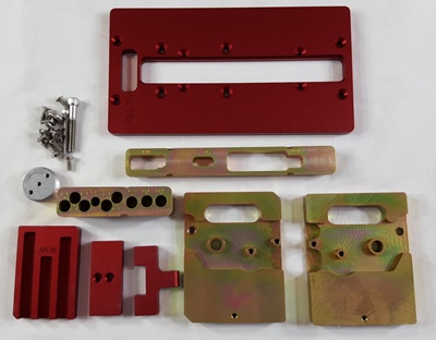
Here's what comes in the Modulus Arms kit. There are two mirror image side plates, a buffer support, front support, rear support, depth gauge plate, top plate, drilling guide insert, routing insert, fourteen short screws, one long cap screw and one large cap screw.
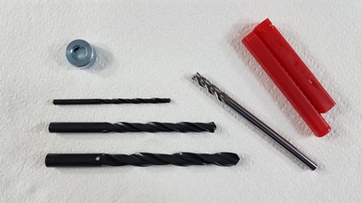
The drill and end mill set that is needed is the same as required by the the previous model and other router-based jigs. A 3/8", 19/64" and 5/32" drill bit, 3/8" stop collar and 1/4" end mill.
Assembling the receiver in the jig:
The Modulus Arms instruction manual begins assembly of the jig by telling the user to install the front pivot pin in the receiver. Installing the front pivot pin is a bit of a pain even for an experienced builder. If the receiver needs to be anodized or painted after machining this pivot pin will need to be removed which is an even bigger pain. I have a YouTube video on assembling a stripped lower receiver and you can view the pivot pin assembly at time mark 9:09. Alternatively I have found you can use a "cotterless hitch pin". Hillman (carried at many hardware stores and Lowe's) has a 1 3/4" version that works well and is about $3. The model is 881123 and the Lowe's item is 138732. 
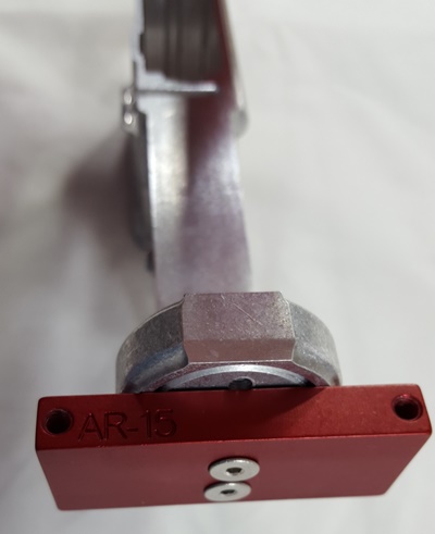 Step two in the manual says to thread in the "buffer support" which is the aluminum disc that threads into the back of the receiver where the receiver extension (buffer tube) would normally go. This provides a base for the rear support to attach to.
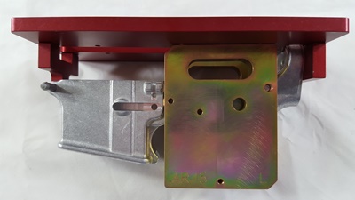
If you are able to easily thread the buffer support you can use two of the screws loosely threaded into the top and bottom buffer support screw holes to help turn the buffer support to just below the end of the receiver. Don't force the buffer support if it doesn't want to go in. I got one stuck in the original jig and had to use a gas wrench (that's a propane torch) to heat the lower and get it unstuck. After threading in the buffer support, and ensuring the three screw holes line up vertically, attach the rear support to the bottom two screw holes. This is different than the standard Modulus Arms jig which has you attach to the top two screw holes. If you attach incorrectly to the top two screw holes with the heavy duty jig it will skew your jig angle and cause depth and alignment issues with your machining. Here is a photo sent in by someone that found out the hard way. Note that depth is too shallow and the buffer retainer hole was partially machined into.
Now attach the top template, recessed holes up, to the four screw holes in the front and rear support pieces. Snug up these screws. I choose to install the front two screws first and then rotate the top plate down onto the rear support.
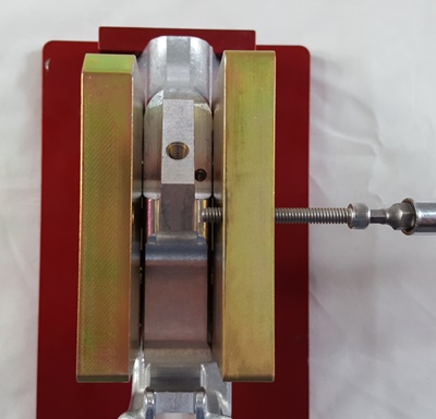
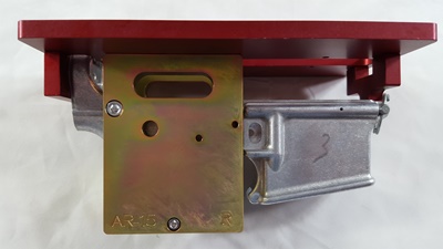
 For the side plates, begin by aligning the two side plates and then insert the four screws into the top screw holes and loosely tighten. Note that the side plates are not identical and are marked right and left. Then squeeze the two plates around the lower and tighten the four screws. Now you can take the thin, long screw and run it through the side plates. Both side plates are threaded so you will be threading these in for a while. You can snug this screw but do not crank on it. The manual says to not install the large screw that goes through the rear takedown pin hole but if your lower already has the rear pocket machined out you can install it (unless you plan to machine the pocket further).
 Now your jig is assembled and ready to begin the machining work. Unlike the original Modulus Arms jig you will not need to disassemble the jig to change out drilling and routing plates. Hooray!
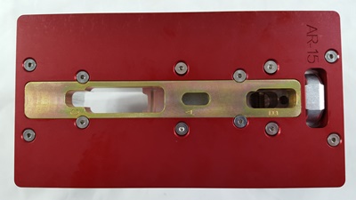
The first piece to assemble in the jig frame is the drilling guide. This guide has a lip that mates with a ridge in the jig and the screw slots can only be inserted one way so you don't have to worry about orientation. Secure the drilling guide insert with two of the short screws.
Begin by drilling the single 9/64" hole ("A") in the drilling guide. This is for the trigger slot and you will want to drill all of the way through the receiver. Next chuck up the 3/8" drill bit and drill out the two rear pocket holes that are also visible in the drilling guide at this time. Only do this if your rear pocket is not already machined AND you have NOT inserted the large screw through the rear takedown pin holes. Set your drilling depth using the depth gauge and the "B" slot. Finally, set your stop collar on the 3/8" bit to the "C" depth on the drilling guide. Drill out the six holes for the fire control group pocket labeled "C" in the drilling guide.
 Now you can unscrew the four screws in the drilling guide to free it from the jig. Insert the routing guide in the orientation shown so the "B" part of the template is towards the rear of the receiver.
NOTE: As with all router jigs on the market the hash marks are a bit too aggressive in my opinion. I recommend only going a 1/2 hash mark at a time and starting a 1/2 hash below the first hash mark. There is less chance of your end mill biting and jumping with these reduced depth millings. It does add some time but the finished product will be worth it.
Place your 1/4" end mill into the router and set the depth of cut to the first hash mark on the "A" depth gauge slot. Insert the end mill through the trigger slot template hole and into the 19/64" hole drilled earlier. Starting in the center of the hole, route outwards until you have milled the entire area at the first cutting depth. Shut off the router, wait for it to stop spinning and then take it out of the jig and set the depth of cut another 1/3 to 1/2 hash mark deep. Repeat the process until you have completely milled out the trigger slot.
If you need to mill out your rear pocket, set the depth of cut on the end mill to the first hash mark on the "B" slot in the depth guide. Mill as before working your way up to the final cutting depth. Make sure you do not have the rear support screw installed in the jig while doing this.
Now remove the four screws from the routing template and turn it 180 degrees so the rear pocket portion is now at the front of the receiver. Re-install the four screws in the routing template.
You can now install the large rear screw between the two side plates and through the rear takedown holes of the lower receiver if they weren't alraedy. This will give added support throughout the remainder of the machining.
Now set the depth of cut on the end mill to the first hash mark on the "C" slot in the depth guide. Mill as before working your way up to the final cutting depth. As you approach the final pass make sure you are starting your end mill over the trigger slot which has been completely milled through. This allows you to start the cutting over air instead of over the coned bottom of the previously drilled 3/8" holes. This is much easier and safer and makes for a cleaner final cut.
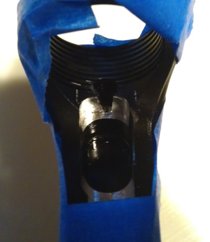
Now it's time to drill the holes for the trigger pin, hammer pin and safety selector. Because of the non-flat nature of the sides of the jig you will need to rig something up to keep the jig flat when drilling with the drill press. Alternatively you can clamp the jig in a vise and use a hand drill to complete these holes. In either case start by drilling one side of the 3/8" hole and once through, switch to the other side of the receiver and drill it out. Do not try to go through both sides of the receiver at once. After that hole is complete switch to the 5/32" drill bit and do the same process. You can now disassemble the jig and remove the lower. Check the fit of your safety lever and trigger/hammer pins and ream out the holes as necessary.
Conclusions: The Modulus Arms Heavy Duty jig is a leaps and bound improvement over their original jig. While the original jig works perfectly well, and is as universal as the new jig, this version solves the usability issues that I believe the first one had. First, the jig is much, much more substantial in weight and material. Thick aluminum with steel inserts should keep this jig lasting a long time. Second, the greater surface area of the new top plate makes it much easier to use with a full-sizer router like I use. I no longer feel I need to use extra care to keep the router from tipping and causing unplanned damage to my lower. Here is a comparison of the top plate dimensions of the 80% Arms Easy Jig and both Modulus Arms jigs
Top plate dimensions:
80% Arms Easy Jig gen2 - 7.5 x 6.125 x 3/16
Modulus Arms original jig - 7 3/16 x 2.5 x 1/4
Modulus Arms heavy duty jig - 8 5/16 x 4 7/16 x 15/16
Third, the elimination of all of the seemingly endless need to assemble, disassemble and reassemble the jig for each step. The steel template inserts make configuring for subsequent steps a simple two or four short screw process. Fourth, the side plates have been made shorter and out of steel so they no longer test the limits of my drill press to fit it in place. Plus the steel makes it unnecessary to be concerned about wearing out the holes on the previous aluminum side plates. Some jigs are made of aluminum with steel drill guide inserts. Modulus Arms went further and just made the whole plate out of steel. I still think the jig should ship with a cotterless clevis pin rather than relying on installation of the front pivot pin or use of a bolt but that's a relatively small matter a simple $3 investment the end user can choose to make.
As with the original Modulus Arms jig, this jig is the only router based design that will handle some of the wilder lower designs out there. Specifically the New Frontier Armory lower comes to mind. This just won't fit in the Easy Jig even with the universal side plates. There's only so much universality you can build into a product that uses full side plates and this jig gets around that by only having partial length side plates.
Let's take a look at the following comparison chart and see which of the reviewed lowers have which features. Click here